

Vessel Management System: VMS

Monitor System’s range of capabilities includes site surveys and analysis, system design, manufacture, installation and commissioning. Significant areas of applications experience and expertise include VMS, RPD, Bulk Tank Control, Tank Gauging, Ballast Control, Machinery Alarm and Anchor Winch Monitoring Systems as well as a wide range of other disciplines.
Work (typical): Project Management / Conceptual Design / QA & HS&E Management / Engineering and Manufacture / System Testing and Software Interrogation / System Documentation, hard copies, CD and online transfer.
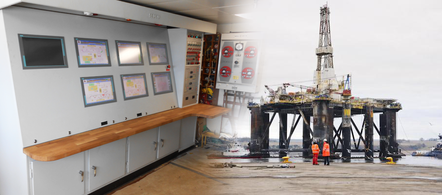
System (typical): Control Console / Custom built console / Console to contain the VMP PLC’s , ET200 I/O, Redundant Servers, IPC’s / Remote I/O Stations / Remote I/O Stations – connected back to PLC dedicated to system equipment / Software Generation / UPS.
Incorporation of the following systems (typical): Ballast Control & Tank Gauging / Brace Leak Detection< / Bilge Pot Flood Detection / Fire & Gas / Fire Damper Control & Indication / Machinery System Control & Indication ( Engines, Compressors etc / Anchor Windlas / Fire Pumps / Deluge System / Bulk Tank Control / Watertight Door Control & Indication / Environmental System / Rack Phase Differential System (Jack-up Only) / System Engineering & Documentation / FAT Test / As-Built Documentation.
Systems Overview: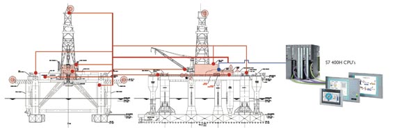
The Ballast Control screen (inset below) allows the operator to control all valves and pumps associated with the ballast system. Pump and valve status are displayed on the screen via a coloured symbol. Control of the pumps and valves is through pop-ups which appear when a specific symbol is ‘selected’. Pump suction and discharge pressures can also be displayed.
The Drain & Bilge screen (inset below) provides a graphical overview for control of the vessels bilge system. Additional bilge systems can be incorporated depending on the vessels configuration. For example the Oily Water Seperator System or the Waste Oil System.
The Tank Gauging screen (inset below) shows an overview of the vessel. Inside each tank is the tank ID as well as the tank level, the percentage of full tank and the tank contents weight. Each tank is colour coded to represent the tank contents, in the bottom right hand quadrant of the screen a key relates to each tank colour with the various types of tanks.
The Vessel’s utilities can also be incorporated into the VMS system. Utilities such as Diesel Oil, Potable Water, Drill Water & Brine etc can all be controlled and viewed through dedicated screens. Separate utilities screens can also be set up to show the tank gauging of all utilities tanks on bar graphs along with visual indication of alarm set-points (inset below). Utilities trending is also an option.
The Vessel Watertight and Weathertight Doors can be displayed as a graphical representation of the vessel allowing the operator to very quickly see the status off the doors (inset below). Control over the Watertight Doors allows the operator to close all doors remotely in emergency situations.
The Fire Damper screen (inset below) shows an illustration of the plan view of the vessel. The location of the Fire Dampers and any associated Remote IO Panels are shown using status indicators upon the plan view and the status indicators change colour depending on the current state of each damper. A red damper indication shows that the damper is open and a green damper indication shows the damper is closed. Green remote IO panel indication shows no fault whereas a red remote IO panel indication indicates a fault with that panel.
Bulk Storage Tanks along with the Surge Tanks are graphically represented on the screen (inset below). Tank contents are also displayed within each graphical image of the tanks. Different coloured lines differentiate between fill, discharge, purge and air supply lines for ease of interpretation. Tank contents can be selected from drop down menus so should the use of a tank change the operator can quickly select the correct bulk product.
Anchor Windlass Control and Monitoring is an example of the vessels machinery systems that can be included into the VMS system. Anchor windlass parameters such as tension, speed and length can be monitored and the windlass operated from the screen (inset below).